Introduction
Recently I’ve got an old computer for free, with the downside however that it wasn’t turning on past the BIOS. After some troubleshooting, it pointed more and more in the direction of a faulty CMOS chip.
So this guide will show you, how to flash your BIOS chip via USB with an Arduino Uno.
Step 1: Check compatibility
Since we are going to use the FlashROM flasher program, please make sure that your BIOS chip is listed in the compatibility list of FlashROM. Basically find the BIOS chip on your mainboard and read off the type number on it.
Please note, that on some mainboards, you first have to remove a sticker from the top of the BIOS chip to read off the type number. In this guide we’ll be using a MX25L8005 CMOS IC by Macronix.
Step 2: Get the BIOS for your mainboard
This step is highly individual and can differ immensely from case to case. However, most times the mainboard manufacturers are offering BIOS images on their websites to be downloaded (mostly in the Driver/Support sections). A simple search with your mainboards model number will guide you there.
In my case I had to search a little longer, considering finding a BIOS download page for the now 13 year old MSI MS-7504 was quite more difficult that I initially thought. Yet I was able to find a suitable ISO file, whose unpacking lead to a .img file, whose unpacking again lead to a FreeDOS environment, containing the long searched BIOS image file named A7504NF1.10Z.
Step 3: Get the necessary packages
Considering that we’re running on Debian, please make sure your system is up-to-date and has the following packages installed to prepare the flashing environment, demanded by FlashROM and the Arduino flasher frser-duino we’re going to use later.
sudo apt-get update
sudo apt-get upgrade
sudo apt-get install git gcc-avr binutils-avr avr-libc avrdude libusb-dev libusb-1.0 libpci-dev
Now that the packages are installed, we can continue to set up FlashROM.
Step 4: Get FlashROM
Since FlashROM is going to be sourced from GitHub, changing to a directory for this specific purpose will help us to keep the setup clean.
cd /usr/local/srcNow clone FlashROM from its repository, compile and install it.
sudo git clone git://github.com/flashrom/flashrom.git
cd flashrom
sudo make
sudo make install
Step 5: Flashing with the Arduino Uno
To make the Arduino Uno suitable to flash BIOS CMOS chips, we firstly have to flash the Arduino Uno itself with the frser-duino programmer. frser-duino is effectively a successor to the serprog-duino programmer project, just to mention as a side note.
Taking into account that the Arduino Uno is equipped with a ATmega8U2 or ATmega16U2 acting as a USB-to-Serial converter for the Arduinos main ATmega328P, frser-duino has to be told to use the 8U2/16U2 conversion and not the standard FTDI USB-to-Serial conversion.
cd /usr/local/srcNow connect your Arduino Uno to your PC via USB, to flash the ATmega328P.
sudo git clone --recursive git://github.com/urjaman/frser-duino
cd frser-duino
sudo make u2
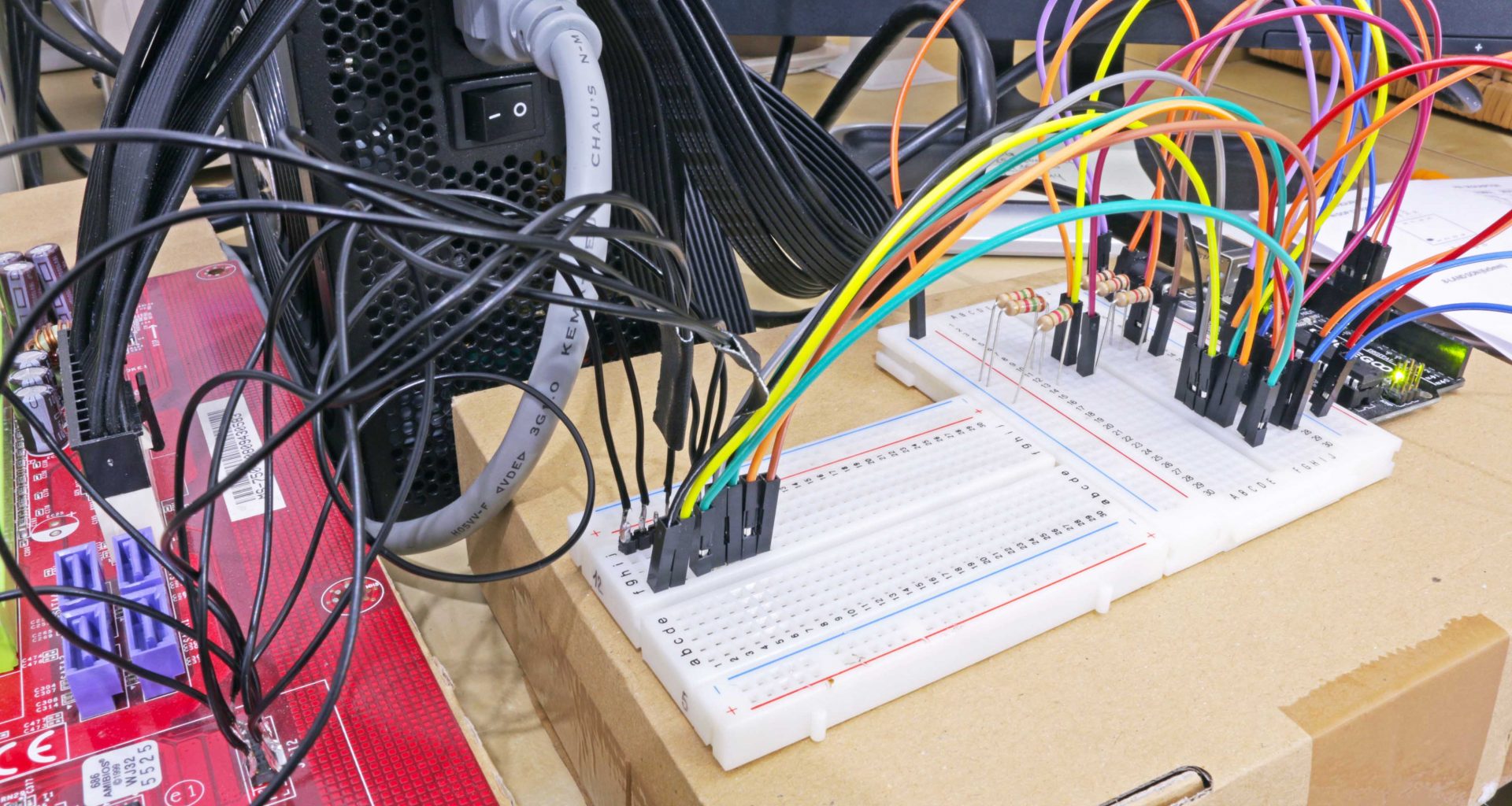
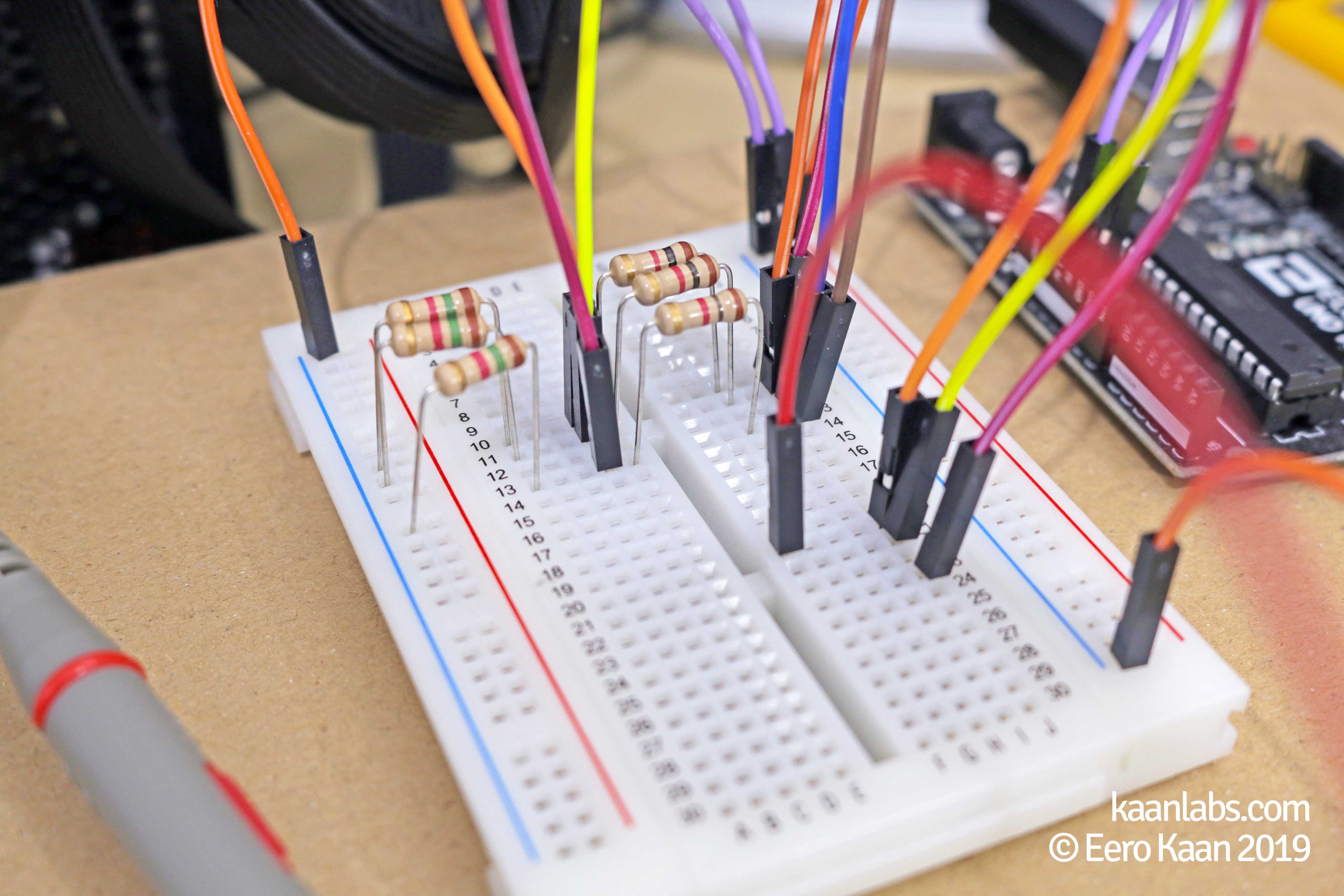
sudo make flash-u2Step 6: Wire up the Arduino to the BIOS chip
Now we have to be extra careful not to destroy the BIOS chip completely by applying a wrong voltage to it. In the most cases, the Arduino Uno logic levels are 0V and 5V respectively, which is too high for most BIOS chips. Please refer to the datasheet of your BIOS CMOS chip for a voltage rating.
The MX25L8005 used in my case for example, is able to handle 2.7V up to 3.6V. Anything above this rating is definitely not healthy for this chip.
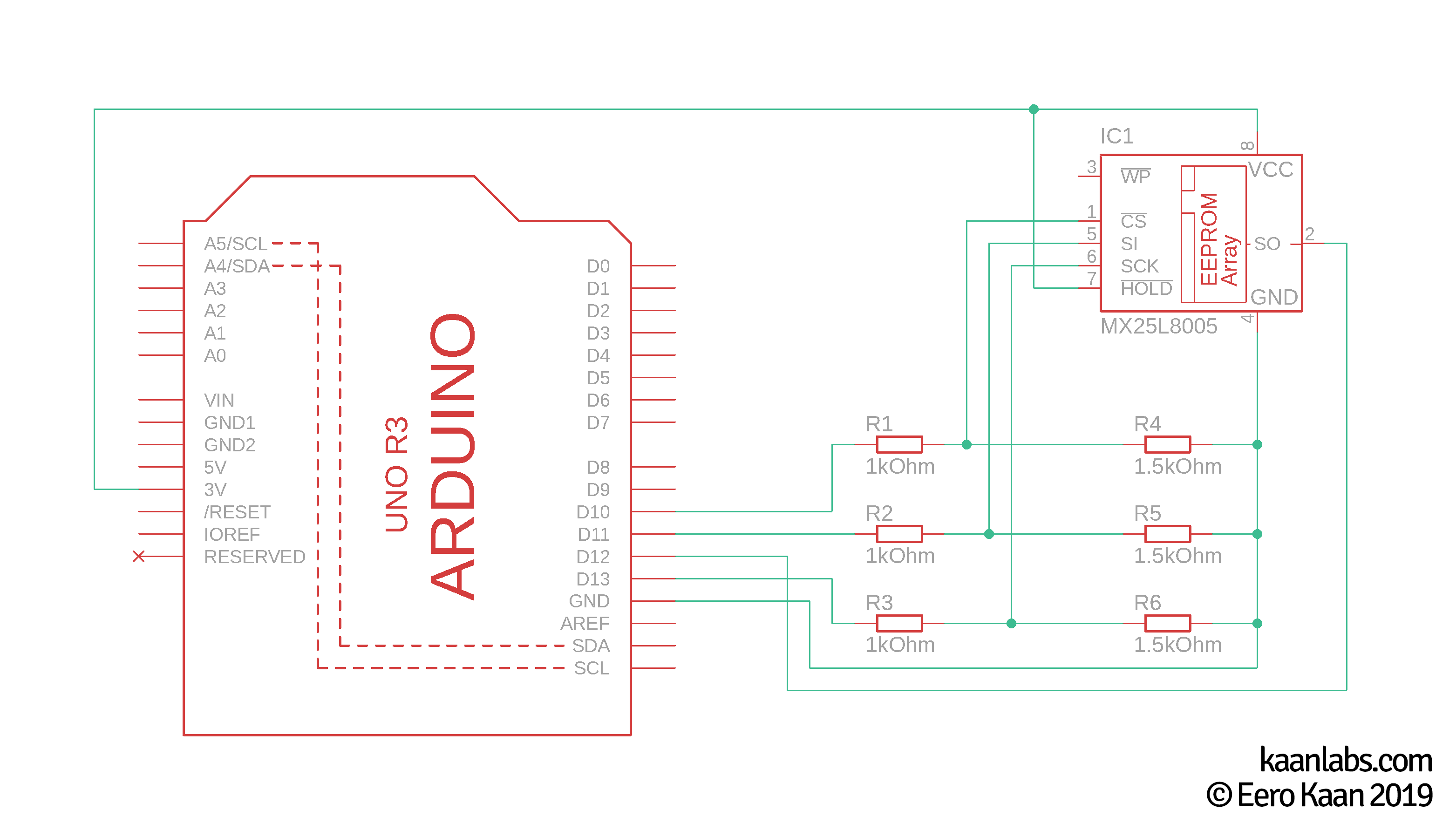
A simple voltage divider on a breadboard is just right to adjust the 5V from the Arduino to the appropriate 3.3V for this BIOS chip. Affected by this alteration are the CS (Chip Select), SI (Serial Input) and SCLK (Serial Clock) pins.
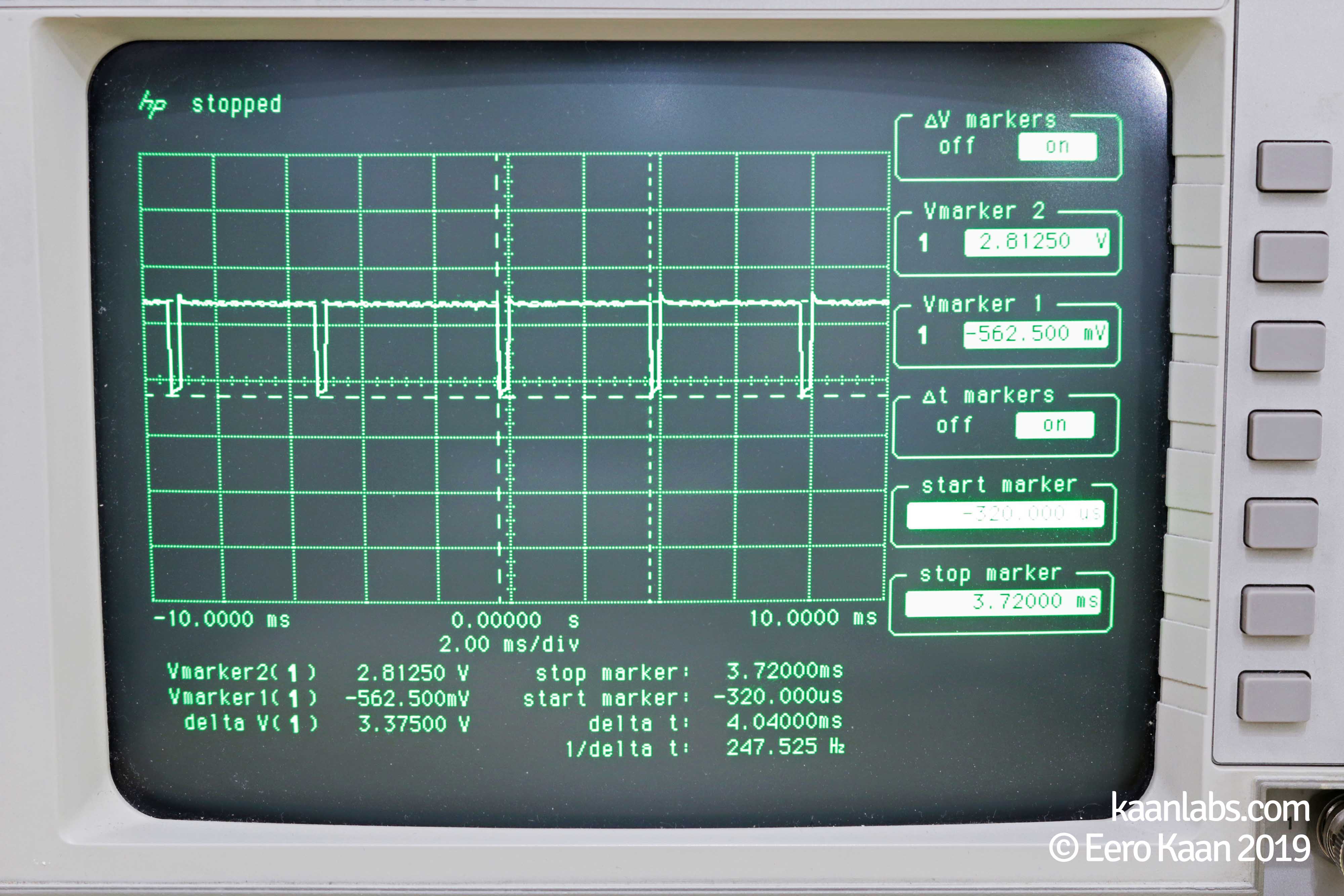
This graph shows how to wire your Arduino Uno to your 3.3V BIOS CMOS chip:
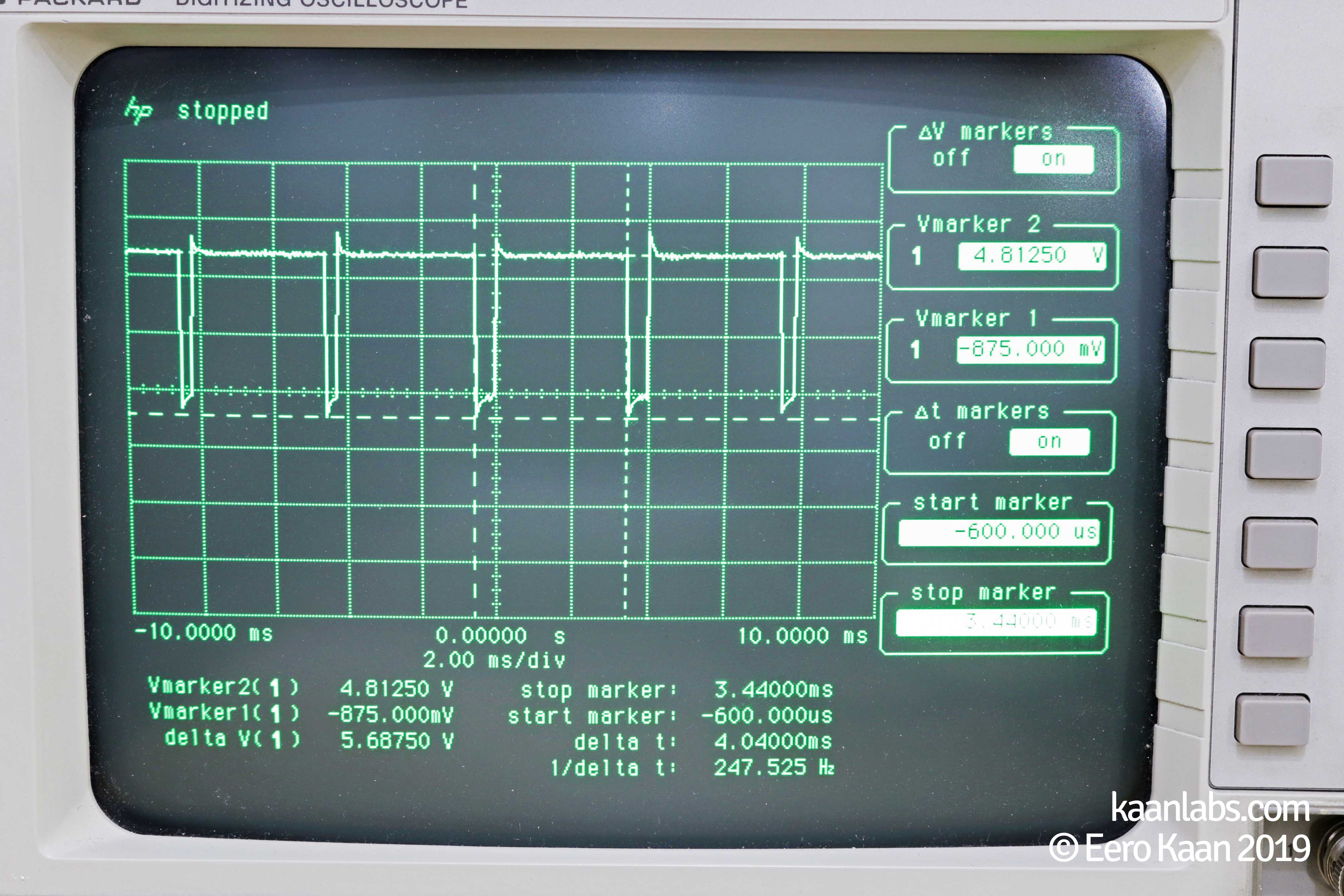
The Oscilloscope shows clearly that the Arduino outputs its 5V quite well. After the voltage divider is implemented, the voltages are much more suitable for the BIOS CMOS Chip:
Step 7: Flash the BIOS chip
Now after everything is wired up, we can now check if the PC is able to detect the BIOS chip:
flashrom -p serprog:dev=/dev/ttyACM0:115200root@debian:/usr/local/src/frser-duino# flashrom -p serprog:dev=/dev/ttyACM0:115200
flashrom v1.1-rc1-2-g93db6e1 on Linux 4.9.0-9-686-pae (i686)
flashrom is free software, get the source code at https://flashrom.org
Using clock_gettime for delay loops (clk_id: 1, resolution: 1ns).
serprog: Programmer name is "frser-duino"
serprog: requested mapping AT45CS1282 is incompatible: 0x1080000 bytes at 0xfef80000.
serprog: requested mapping IS25LP256 is incompatible: 0x2000000 bytes at 0xfe000000.
serprog: requested mapping IS25WP256 is incompatible: 0x2000000 bytes at 0xfe000000.
Found Macronix flash chip "MX25L8005/MX25L8006E/MX25L8008E/MX25V8005" (1024 kB, SPI) on serprog.
serprog: requested mapping MX25L25635F is incompatible: 0x2000000 bytes at 0xfe000000.
serprog: requested mapping MX66L51235F is incompatible: 0x4000000 bytes at 0xfc000000.
serprog: requested mapping MX25U51245G is incompatible: 0x4000000 bytes at 0xfc000000.
serprog: requested mapping N25Q256..3E/MT25QL256 is incompatible: 0x2000000 bytes at 0xfe000000.
serprog: requested mapping N25Q512..3E/MT25QL512 is incompatible: 0x4000000 bytes at 0xfc000000.
serprog: requested mapping S25FL256S......0 is incompatible: 0x2000000 bytes at 0xfe000000.
serprog: requested mapping W25Q256.V is incompatible: 0x2000000 bytes at 0xfe000000.
serprog: requested mapping W25Q256JV_M is incompatible: 0x2000000 bytes at 0xfe000000.
No operations were specified.As Line 10 suggests (Found Macronix flash chip "MX25L8005 [...]), the chip is now detected.
In this state, we are now able to flash the BIOS binary to the chip. Just select the previously downloaded binary with FlashROMs -w Parameter and execute the command.
flashrom -p serprog:dev=/dev/ttyACM0:115200 -w A7504NF1.10Zflashrom v1.1-rc1-2-g93db6e1 on Linux 4.9.0-9-686-pae (i686)
flashrom is free software, get the source code at https://flashrom.org
Using clock_gettime for delay loops (clk_id: 1, resolution: 1ns).
serprog: Programmer name is "frser-duino"
serprog: requested mapping AT45CS1282 is incompatible: 0x1080000 bytes at 0xfef80000.
serprog: requested mapping IS25LP256 is incompatible: 0x2000000 bytes at 0xfe000000.
serprog: requested mapping IS25WP256 is incompatible: 0x2000000 bytes at 0xfe000000.
Found Macronix flash chip "MX25L8005/MX25L8006E/MX25L8008E/MX25V8005" (1024 kB, SPI) on serprog.
serprog: requested mapping MX25L25635F is incompatible: 0x2000000 bytes at 0xfe000000.
serprog: requested mapping MX66L51235F is incompatible: 0x4000000 bytes at 0xfc000000.
serprog: requested mapping MX25U51245G is incompatible: 0x4000000 bytes at 0xfc000000.
serprog: requested mapping N25Q256..3E/MT25QL256 is incompatible: 0x2000000 bytes at 0xfe000000.
serprog: requested mapping N25Q512..3E/MT25QL512 is incompatible: 0x4000000 bytes at 0xfc000000.
serprog: requested mapping S25FL256S......0 is incompatible: 0x2000000 bytes at 0xfe000000.
serprog: requested mapping W25Q256.V is incompatible: 0x2000000 bytes at 0xfe000000.
serprog: requested mapping W25Q256JV_M is incompatible: 0x2000000 bytes at 0xfe000000.
Reading old flash chip contents... done.
Erasing and writing flash chip... Erase/write done.
Verifying flash... VERIFIED.And that’s it! If you have the same/similar console output as above, you are now finished.
Congratulations, you now flashed your BIOS chip via USB over an Arduino Uno.
Step 8 (Optional): Replace your BIOS chip
If you got errors however like I had on the first try, it is likely that your BIOS CMOS chip is broken on a hardware level. In this case, you have to physically desolder the CMOS chip from the mainboard and replace it with a new one (the same model that is).
Such a error message can look something like this:
root@debian:/usr/local/src/frser-duino# flashrom -p serprog:dev=/dev/ttyACM0:115200 -w A7504NF1.10Z
flashrom v1.1-rc1-2-g93db6e1 on Linux 4.9.0-9-686-pae (i686)
flashrom is free software, get the source code at https://flashrom.org

Using clock_gettime for delay loops (clk_id: 1, resolution: 1ns).
serprog: Programmer name is "frser-duino"
serprog: requested mapping AT45CS1282 is incompatible: 0x1080000 bytes at 0xfef80000.
serprog: requested mapping IS25LP256 is incompatible: 0x2000000 bytes at 0xfe000000.
serprog: requested mapping IS25WP256 is incompatible: 0x2000000 bytes at 0xfe000000.
serprog: requested mapping MX25L25635F is incompatible: 0x2000000 bytes at 0xfe000000.
serprog: requested mapping MX66L51235F is incompatible: 0x4000000 bytes at 0xfc000000.
serprog: requested mapping MX25U51245G is incompatible: 0x4000000 bytes at 0xfc000000.
serprog: requested mapping N25Q256..3E/MT25QL256 is incompatible: 0x2000000 bytes at 0xfe000000.
serprog: requested mapping N25Q512..3E/MT25QL512 is incompatible: 0x4000000 bytes at 0xfc000000.
serprog: requested mapping S25FL256S......0 is incompatible: 0x2000000 bytes at 0xfe000000.
serprog: requested mapping W25Q256.V is incompatible: 0x2000000 bytes at 0xfe000000.
serprog: requested mapping W25Q256JV_M is incompatible: 0x2000000 bytes at 0xfe000000.
Found Generic flash chip "unknown SPI chip (RDID)" (0 kB, SPI) on serprog.
===
This flash part has status NOT WORKING for operations: PROBE READ ERASE WRITE
The test status of this chip may have been updated in the latest development
version of flashrom. If you are running the latest development version,
please email a report to flashrom@flashrom.org if any of the above operations
work correctly for you with this flash chip. Please include the flashrom log
file for all operations you tested (see the man page for details), and mention
which mainboard or programmer you tested in the subject line.
Thanks for your help!
Error: Image size (1048576 B) doesn't match the flash chip's size (0 B)!
After replacing the chip, just jump back to step 6 and try again.
3 comments
Thanks dude, it worked. Great tutorial.
Hi Jaden,
looks that your downloaded BIOS-File isn’t referenced correctly. As the message
No such file or directoryimplies, the BIOS-File isn’t located in your current working directory, but rather as you mentioned in your default download directory. Assuming you’re using Debian/Ubuntu, the correct command would beflashrom -p serprog:dev=/dev/ttyACM0:115200 -w ~/Downloads/P9X79.CAP.Hey man, great tutorial. I’m stuck at the last part though. When I type in
-w P9X79.CAPit puts out that it found the chip but then says this:Error: opening file "P9X79.CAP" failed: No such file or directory. So how can I get this? I downloaded it into my downloaded files. Thanks for the tutorial and would love If you could help me. Thanks!